- Hardware
- 802.15.4/Zigbee
- CAN
- Ethernet
- USB
- Other
- Software
- Android
- Web
- PC/Others
- Hard/Software
- Other/Mechanical
- Documents
Dimmer for lights in apartment controlled via USB and/or IR.
Status: Done, in use. Depricated, replaced by lightdimmer30
| Date | Comment |
|---|---|
| 2006-03-05 | Added a “in action” movie. (see Downloads) |
| 2006-01-22 | Added more photos. |
| 2005-08-01 | Project created. |
The light dimmer can handle up to eight loads and control the voltage from 0V to 230V induvidually foreach load by giving it a integer value between 0 to 199. A load can be a regular lightbulp, halogen lamp or any other resistive load with a power consumtion of max 500W. The loads are controlled from either a PC using a controller application or by using a regular remote control.
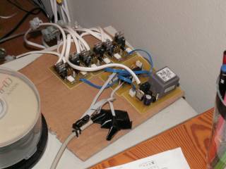
The hardware is module based with three modules, the high voltage module, the controller module and the dimmer module.
 Hardware module. The high voltage module transform the 230VAC to 12VAC using a 12V 2.6VA tranformer and is rectified and regulated to 5VDC. Also, it has a zero crossing unit that creates a pulse (galvanic seaparated) every time the 230V sine wave crosses the zero volt level.
 Dimmer module. Each dimmer module has two channels and are galvanic seperated (using optocoupler) from the controller unit. Each channel has two IRF830 MOSFET:s which are pulse modulated from the controller unit. On each zero crossing the MOSFET:s are turned on, and by waiting a variable amount of time, that is cutting out a part of the sine wave,before turning them off, a variable voltage output is achived. (The module on the photo differs from the final layout which can be seen in the assambled photo below)
 Controller module. The controller module has a IR-interface for controlling the lights by remote control. Currently, only Philips RC-5 are supported, but other protocol are easly added. The controller, a PIC18F2550 (in picture a PIC18F252), can work stand-alonge just using a remote control, but it's supposed to be connected to a computer using USB. The controller take care of timing for each channel, reciving of IR commands and commands from the computer based controller application.
 Entire system connected to the computer using rs232 and with five lamps connected.
The firmware is written in Microchip's C18 V 3.0 using MPLAB 7.21 and microchips USB-stack as a base.
Latest source code and schematic/PCB-layout can be found in repository
/software/trunk/PC/lightdimmer/ ,
/software/trunk/Embedded/lightdimmer/ and
/hardware/trunk/schematics/lightdimmer/ in SVN.
A movie can be found here.
All information found on this page are licensed. See the license page for more information.